현재 자작 전기차를 제작하고 있어 자동차 모터 온도를 측정하기 위한 서미스터를 이용한 블루투스 온도계를 제작하였다.
혹시 몰라서 디바이스마트에서 MAX6675 K타입 모듈을 따로 주문하였지만, 일시적으로 사용할 수 있는 것은 모터에 장착된 서미스터을 이용하는 방법밖에 없었기에 이 방법을 택하였다.


서미스터(Thermistor)란?
자동차 제작에 사용된 모터는 Saietta Motors의 119R이라는 모델이다.

본 모터에 장착된 서미스터는 실측 결과 2K Ohm으로 나왔기 때문에 회로에도 동일한 2K Ohm을 사용한다.
그리고 본 모터에 사용된 서미스터는 NTC(Negative Temperature Coefficient) 서미스터로 온도가 증가하면 저항값이 감소하는 전기적 장치이다.
우선 모터에 사용되는 서미스터에 대한 정보를 알아보아야 한다.
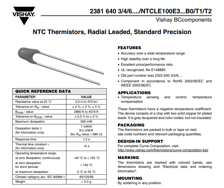
표를 보면 운용 온도와 오차율 확인이 가능하다.
이제 실제로 사용할 온도계의 회로를 구성한다.

회로는 다음과 같이 구성해준다. 여기서 서미스터와 똑같은 값의 저항을 장착해주고 그로부터 나오는 전압을 측정하여야 한다. 전압 측정은 Analog In 포트를 사용한다.
왜 하필 저런 식으로 회로를 구성해야 해 주는가에 대해서는 전압 분배 법칙을 참고하면 된다.
Vout=Vin∗R2R1+R2 V_{out} = V_{in}* \frac {R_2} {R_1 + R_2}

위와 같은 식이 나오게 된다. 여기서 서미스터의 저항과 같은 저항을 사용해주면 안정적으로 측정이 가능하다.
참고로 아두이노가 수용 가능한 전압은 5V까지이다.
이제 온도를 측정하는데 필요한 식을 알아보자.
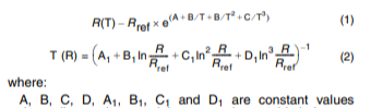
NTC 써미스터 Spec Sheet에서 가져온 식이다. 이는 Steinhart-Hart Equation으로 저항과 온도와의 관계를 표현하는 식이다. 관련 링크는 여기에!
https://en.wikipedia.org/wiki/Steinhart%E2%80%93Hart_equation
Steinhart–Hart equation - Wikipedia
From Wikipedia, the free encyclopedia Jump to navigation Jump to search The Steinhart–Hart equation is a model of the resistance of a semiconductor at different temperatures. The equation is 1 T = A + B ln R + C ( ln R ) 3 , {\displaystyle {\frac
en.wikipedia.org
이제 온도계 구현에 필요한 라이브러리는 블루투스를 위한 SoftwareSerial과 math이다.
여기서 한 가지를 더하였다. 그것은 바로 Low-pass Filter(LPF)이다.
LPF 설명은 아래에 영어로 적혀있지만 짧게 말하면 고주파 잡음을 걸러주는 필터이다.
A low-pass filter (LPF) is a filter that passes signals with a frequency lower than a selected cutoff frequency and attenuates signals with frequencies higher than the cutoff frequency.

여기서 fc 즉 Cutoff Frequency는 5hz를 사용하였다.
#include <SoftwareSerial.h>
#include <math.h>

int Tx = 6;
int Rx = 7;

SoftwareSerial BtSerial(Tx,Rx);


// Need 2K ohm to connect Motor's Thermistor

#define ANALOG_PIN_TIMER_INTERVAL 2 //milliseconds

unsigned long thisMillis_old;

int fc = 5; // Cutoff Freq 5Hz
double dt = ANALOG_PIN_TIMER_INTERVAL/1000.0; // sampling time
double lambda = 2*PI*fc*dt;
double temp_unf = 0.0;
double temp_f = 0.0; // filtered Data
double temp_fold = 0.0;


static long analogPinTimer = 0;

const int thermistorPin = A0;
// Parameter for 33K ohm
//double ParamA = 0.00335401600;
//double ParamB = 0.00025191070;
//double ParamC = 0.000003510939;
//double ParamD = 0.0000001105179;

// Parameter for 2K ohm

double ParamA = 0.003354016;
double ParamB = 0.0002933908;
double ParamC = 0.000003494314;
double ParamD = -0.0000007712690;

void setup() {
  // put your setup code here, to run once:
  Serial.begin(9600);
  Serial.println("Connects complete");
  BtSerial.begin(9600);

}

void loop() {

  unsigned long deltaMillis = 0;
  unsigned long thisMillis = millis();

  if (thisMillis != thisMillis_old) {
    deltaMillis = thisMillis-thisMillis_old;
    thisMillis_old = thisMillis;
  }

  analogPinTimer -= deltaMillis;

  if (analogPinTimer <= 0) {
    analogPinTimer += ANALOG_PIN_TIMER_INTERVAL;
  }

  int readVal = analogRead(thermistorPin); // Read data
  double temp_unf = Thermistor(readVal);
  temp_f = lambda/(1+lambda)*temp_unf+1/(1+lambda)*temp_fold; // filtered Data
  temp_fold = temp_f; // update data
  int tempC = temp_f - 273.15;
  int tempF = (tempC*9.0) / 5.0 + 32.0;

//
//  int readVal = analogRead(thermistorPin);
//  double temp = Thermistor(readVal);
//  double tempC = temp-273.15;
//  double tempF = (tempC*9.0) / 5.0 + 32.0;


  Serial.print(tempC);
  Serial.println(" C");

  if (BtSerial.available()) {
    Serial.write(BtSerial.read());
  }
  // Serial -> Data -> BT
  if (Serial.available()) {
    BtSerial.write(Serial.read());
  }

  BtSerial.println(tempC);
  delay(300);
}

double Thermistor(int RawADC) {
  double Temp;
  Temp = log(10000.0*((1024.0/RawADC-1))); // 1024 = 아두이노 분해능 , Rt
  Temp = 1 / (ParamA + ( ParamB + ( ( ParamC  + ParamD * Temp) * Temp * Temp )) * Temp );
  return Temp;

}
코드는 다음과 같이 구성되어있다. 회로도에서는 0,1번에 Rx, Tx를 하였지만 실제로 제작할 때 6,7번 핀에 블루투스 모듈을 연결하였다. 위에서 Parameter가 있을 텐데 이는 데이터 시트의 Parameter 표를 통해서 구하였다.

다음에는 Max6675를 이용하여 TM1637 FND에 정보를 띄우는 것을 포스팅할 예정이다.
'Embedded > Arduino' 카테고리의 다른 글
| [Arduino] 아두이노로 자작자동차 속도계 및 온도계 제작하기 (8) | 2020.10.15 |
|---|